Cool performance
Sipa optimises cooling systems on preform tooling to cut customer costs and enhance sustainability
The sums are simple: productivity goes up, costs come down, carbon footprint gets smaller when you cut cycle time in preform production. Any reduction in specific energy consumption makes the process more sustainable. Plus, optimisation of water consumption leads to further falls, not only on this precious natural element but also in energy expenditure, as it reduces the electricity consumption of the pumps that feed the cooling circuits. This opens up the possibility of using smaller pumps, with another improvement in sustainability. Engineering and manufacturing in-house a huge number of PET preform moulds every year, Sipa claims to not only understand these sums, but to know how to put them into practice.
The key elements that brought Sipa to a leading position on this application are the consolidated experience both on the engineering and manufacturing steps as well as the flexibility to engineer the tooling accordingly to the specific preform design and features.
Considering all variables
To provide maximum flexibility, Sipa engineers consider multiple variables, including the layout of the mould — the number of cavities, horizontal pitch, vertical pitch, and so on. What results is a robust mould design that is suitable for whatever machines the customer has on their production floor.This concept of customisation is transferred into the complete mould development process, virtually from the moment the idea of the product is born, throughout the development of the application with the customer. Cooling circuits is one of the most important aspects that is considered right from the start.
It goes almost without saying that the cooling system is designed not only in relation to the size of the mould and the machine, but also in relation to the geometry of the preform. Typically, based on the productivity objectives set by the customer, and the injection machine that they have available, reference is made to a specific layout (number of cavities, pitch and arrangement), each of which has a standardised architecture: this makes it possible to achieve various objectives of compatibility between the various components (between the mould cold half and the hot runner system, for example).
Sipa, however, does not limit itself to applying a standard solution likely to provide satisfactory performance for any application. Instead it intends to create an optimal level of performance to meet every customer requirement. This requires checking that the cooling water distribution diagram is ideal for the specific application and, if necessary, applying corrective solutions in order to obtain a fully optimised result. In each and every case, one important job that is always carried out is optimisation of the stack cooling to ensure the best result in all its aspects.
Results:
- diagram of the water circuit always optimised for each plate in order to provide the right amount of water for each cavity, distributing it evenly;
- cooling design of stack components always optimised, to obtain the best cooling performance with lowest energy consumption.
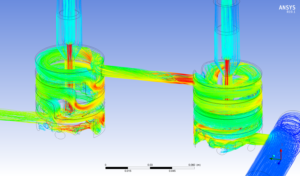
Customised cooling design trough the FEA
Dimensioning of every individual system is strongly supported by Finite Element Analysis (FEA) to evaluate the thermal and fluid dynamics of that system. Each plate has a personalised water diagram and each stack has a dedicated design. The reason, according to Sipa, is to make use of the best software systems currently on the market and customise them to provide high-speed mould analysis. This activity is incorporated into the engineering development flow, without having an impact on the lead time of the product. The impact that it does have is in the creation of a product with high performance, both in terms of cycle time and consumption in utilities that are all 100% tested internally before delivering the tool to the customer.
Mapping characteristics
Validation of the various analytical evaluations is carried out during the first stages of testing. Before conducting any functional testing, the moulds that are designed and built on the basis of these calculations are subject to measurements of the characteristic curves of flow rate and power on a special test bench. This activity is important, because it allows for validation of the project assumptions, and to increase the capacity of Sipa’s database through the acquisition of new experiences, further refining the calculation methods behind the company’s mould design capabilities.
Sipa offers various adaptation kits that allow the installation of the same mould on different models of injection moulding machine to make customer operations as flexible and economical as possible. The benefits of the state-of-the-art Sipa toolings are accessible globally to all preform producers, since Sipa preform moulds can be interfaced with the vast majority of injection moulding machines that are used in this application.