Machine Details, Blow Moulds
Stretch Blow Molding, part 12
by Ottmar Brandau
Ottmar Brandau has newly revised his book “Stretch Blow Molding”, first published by hbmedia / PETplanet Publisher, and now re-issued in a third edition under the Elsevier Imprint. PETplanet Insider is publishing extracts from successive chapters in a serie of articles.
Air Consumption
Another important feature is air consumption and more specifically the so-called dead air volume. Air is the single-most costly part of blowing bottles besides the preforms and users do well to pay close attention to this issue.
Air consumption is driven by the air pressure, the actual volume of the bottles produced, and the air that is not used in the blow process but needs to be exhausted every blow cycle. This air “hides” in the connection pieces between the blow valves and the cavity. When the exhaust valve is energised, all air that is between it and the cavity must be exhausted besides the actual bottle volume to make sure there is no pressure left in the blown bottle. Many manufacturers of blow machines do not publish this important information but users can calculate it by looking at the machine specifications.
Let us assume a manufacturer specifies blow air consumption of 1,300 Nm3/h for the production of 20,000 b/h of 1.5 l volume at 35 bar. The volume that is actually inside the bottles is 20,000 b/h × 1.5 l × 35 bar/1,000 l/m3 = 1,050 Nm3/h. The difference of 1300-1050 = 250 Nm3/h is the dead air volume. This in turn is 367 ml/bottle (250 Nm3/h × 1,000 l/ Nm3/h/20,000 b/h/35 bar). It is important to calculate this as a fixed number rather than a percentage as this lost air is present for bottles of each size. A 500 ml bottle has the same losses as a 1.5 l bottle; however, in the case of the smaller bottle 73% more blow air is needed than would be if just the bottle needed to be supplied. Smaller dead air volumes will save significant money over the lifetime of the machine. Small machines particularly often feature high dead air losses and users should carefully examine manufacturers’ offerings (Fig. 4.19).
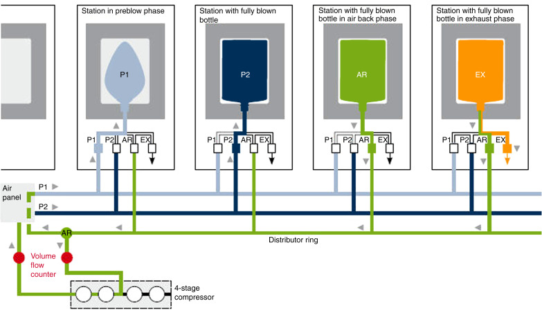
There is one more source of needed air volume that is not mentioned yet. On some machines that use pneumatic cylinders for stretch rod activation, this air is actually high-pressure blow air that is reduced to the 8 bar or so that the stretch rod cylinders are using. While compressing air to 35 or 40 bar and then reducing it to 8 or 10 bar is an expensive undertaking, this is done to avoid adding another line to the distributor inside the blow machine as this distributor for air, water, and electrical power is one of the most expensive parts of the blow moulding machine. The newest machines with servo or electromechanically controlled stretch rods do of course not use any air and will save money in the long run.
Because of the cost of air consumption, most companies now offer air-recycling systems. These systems, instead of exhausting blow air into the atmosphere, pipe it back to a storage tank where it can then be used for preblow and stretch rod air, the machine air circuit, or other plant air requirements. Of course, pressure reducers in the systems allow the proper pressure for the various uses. In this manner, savings of 25–50% can be achieved. This not only reduces operational costs but also helps with capital expenses as fewer or smaller compressors may be needed. A small cycle time penalty is unavoidable because the air does not move as fast to the pressurised storage tank as it does to the lower atmospheric pressure.
5. Blow Moulds
Blow moulds play a large part in making high-quality bottles. While the machine has to deliver preforms at the right temperature, it is the blow moulds that give containers repeatable features and a brilliant appearance (Fig. 5.1).
5.1 Design

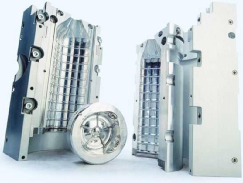
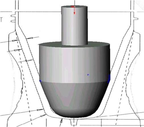
Neck and thread finish are already formed in the preform; so blow moulds form only the body and base of the bottle. In the reheat stretch blow moulding (RSBM) process they consist of three parts: two mould halves and one base insert (also called push-up). The base insert is necessary because the walls at the base of the concave container could not slide over the mould halves during mould opening if these were forming them. Instead, the vertically moving base insert is drawn out of the way before, or as, the mould opens (Fig. 5.2).
While the three-piece design is common to all moulds, they are manufactured quite differently depending on the type of machine to which they will be fitted. Linear machines have all mould cavities mounted within two blocks where the cavities sit side by side. In rotary machines each blow mould is mounted to a separate carrier, opening and closing individually. Modern machines use so-called shell moulds whereby the actual mould halves are only 5 mm thick and are assembled onto bases that are all the same for a family of containers. These bases carry all water connections and need not be touched during a changeover, thus reducing valuable time.
Moulds are usually built from aluminium, which is chosen for its high heat transfer rate, easy machinability, and lightweight. The types of aluminium used are typically those used in the aircraft industry. AL 7075 T6, T-2024, or Alumenec 89 are some of the grades used worldwide for this application. Base inserts may be of the same material or made from beryllium–copper.
Another material in use is stainless steel for hot-fill applications. While a polish to mirror-like quality is still the norm, some companies have quite successfully tried to leave moulds at a much rougher polishing state. This saves cost because the mirror polish is still applied manually while detracting only very slightly from the expected bottle surface appearance.
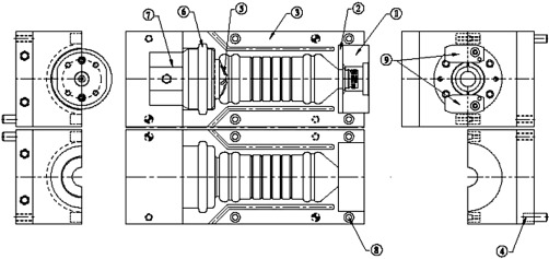
The internal pressure of the blow air results in a considerable force against the closing mechanism of the blow mould. Blow moulds have guide pins and bushings as well as taper locks in the base insert that keep the mould in position during the blow process. Mould carriers feature locking mechanisms that keep them closed against the blow pressure. To alleviate these stresses and also make ever-lighter frames possible, “pancake” cylinders have become increasingly popular. These cylinders are very thin shells behind the blow moulds and are filled with the same air that blows the bottle. Since pressure is equal both inside and outside the mould there is no resultant force acting against the mould halves (Fig. 5.3).
5.2 Base Mould
Today, all base moulds feature a small recess like a well in the center. This allows some room for the protruding injection gate on the preform. Keeping the gate in the center of the mould is probably the most important task in the blow process because any deviation from the center leads to uneven wall thickness variation. The well catches the injection gate and prevents it from slipping as long as there is enough pressure from the stretch rod.
In many custom applications the bottle bottom is thicker than is really needed but because of preform design or machine insufficiencies it ends up like that. In these cases it is often the cooling of the bottle bottom that controls the cycle time. Proper cooling is therefore crucial to come to a cost-effective solution with fast cycles. Cooling lines should not be smaller than 6 mm in diameter (unless of course there is no room in very small bottles) and the flow path should have no restrictions. High water supply pressure with low water return pressure are also helpful (Chapter 13, Section 13.2).
5.3 Making a Mould
Today’s mould-making process starts with a three-dimensional (3D) computer model of the container itself. Physical models may be made by a variety of processes, the most popular still being stereo lithography with 3D printing catching up quickly because of the availability of low-cost printers. The model may be used to give marketing people a better “feeling” for a new container. Once approved, data of the computer model are then fitted in a new or existing mould base. At this point, shrinkage has to be added to the container dimensions. Polyethylene terephthalate (PET) shrinks approximately 0.08% but shrinkage is not uniform and it is the experience of the mould maker that determines how closely the capacity of the container matches specification.
A variety of computer-aided design (CAD)/ computer-aided manufacture (CAM) programs allow the creation of machine cutter paths that are downloaded directly into high-speed machining centers. Machine operators load and center blocks of aluminium of suitable size and special cutters, spinning at up to 30,000 r.p.m., move at a speed of up to 20 m/min. The resulting cavity surface is already smooth to the eye but most mould makers add a high, mirror-like polish, which still requires skilled, manual labour. The use of sandblasted surfaces that are common in other plastic processes has gained some ground as there is little difference in the appearance of the containers. Some mould makers then coat the cavity surfaces with various materials, often containing nickel and Teflon, to give it abrasion resistance.
5.4 Venting
Venting is another area where the experience of the mould maker becomes extremely important. Because PET fills the mould cavity during blowing, the air inside the cavity must be exhausted. For this purpose mould makers add a variety of vents. Compared to other processes, such as injection moulding or extrusion blow moulding, PET is processed at a relatively low temperature in the RSBM process. Vent sizes are limited to 0.04 mm (0.0015 in.) in injection moulding but vents of up to 0.5 mm (0.020 in.) are used in RSBM with hole vents up to 1 mm (0.040 in.). All moulds have vents on the contact surface of the cavities. One mould half is typically completely recessed against the mould base by up to 0.20 mm (0.08 in.) or more commonly by 0.15 mm (0.006 in.). Base vents are also common and are accomplished by leaving the base insert to move 0.25–0.3 mm (0.010–0.012 in.) downward under the force of the stretch rod. The resulting ring-shaped gap between base insert and mould cavity allows air to escape.
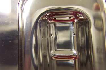
Hole vents up to 1 mm are used in areas where air entrapment is suspected. Vents of this diameter may not show in areas where the material has stretched and consequentially strain-hardened but will show as small dimples where this is not the case. A common example of highly stretched material is the foot of a petaloid base for carbonated soft drinks (CSD) containers. Two small holes in each foot let air escape that might otherwise be trapped by the material flowing around it (Fig. 5.4).
Another use of venting is to direct PET into hard-to-blow areas. In a highly oval bottle, for example, there is always the possibility of a ridge of higher wall thickness forming at the center of the narrow side of the container. Vent holes at the far side of the mould can attract PET to flow more quickly into these areas, thereby stretching out the preform walls close to the narrow side. A fine sandblast finish instead of the mirror-finish also helps to let the air move out of the mould.
Due to low temperature in the RSBM process compared with uses in other processes, PET does not flow easily into small mould crevices. Minimum dimensions for female radii might be given as 0.8 mm (1/32 in.) but it will depend on the stretch ratio of the PET flowing toward it whether it will fill out or form a greater radius instead. Male radii should be double that amount especially when used in bases. Here a sharp radius may cause a crease in the material and open the door to stress cracking. Venting in these areas can be attempted to reduce the risk of air entrapment stopping the advance of the parison but more often than not they do not seem to have much effect. We will simply have to live with the fact that PET benefits from more generous radii in this process.
5.5 Stretch Rod

In two-stage moulding stretch rods are typically made of solid Stainless Steel with sizes 9–16 mm (3/8–5/8 in.). Stretch rod diameters are often limited by the neck size and larger rods should always be used when the neck size allows it. This facilitates the exact placing and holding of the gate in the center of the mould. A downside of a large stretch rod diameter is that the surface of the rod cools the area it touches on the preform. Lightweight water bottles, for example, need the base totally stretched and a large rod diameter may prevent that from happening. On the other side, making a rod too thin would lend it to easy bending. As a consequence, rods are made to keep the larger diameter in the upper portion to prevent bending but are reduced in diameter in the area of the preform (Fig. 5.5).
In single-stage moulding, stretch rods often have tips screwed on at the end. These could be made from aluminium or nylon. On machines without conditioning, they can also be used to cool the bottom of the preform, just the opposite function they have in two-stage moulding. This is useful because the bottom of the preform is often the hottest part and may lead to thin bottoms. A large tip made from aluminium can be placed into the preform a few seconds before the mould is closing. This does not lead to a cycle time increase as the blow cycle is always faster than the injection cycle. The timer “delay mould close” is used to achieve this effect (Fig. 5.6).